Mounting Techniques
The following subjects are described below:
- Standard O-Ring Groove
- Groove Corners
- Dovetailed O-Ring Groove
- O-Ring Groove with Adhesive
- O-Ring Groove with Pinch Bosses
- Narrow O-Ring Groove
- Groove Mounting Other Gaskets
- Groove Dimensions
Information is also available on Surface Mounting Techniques.
View Mounting Techniques datasheet in pdf format.
Please Note: We have a paper on Cost-Effective Grooves (in pdf format) that explains how to choose the best groove for your application. This paper includes specifications and new information on all four types of grooves including the"pinch boss" which can be very cost effective for molded or die cast applications.
Spira Gaskets are made from spring temper tin plated beryllium copper or stainless steel. The advantage of using these materials is that the gasket acts as a spring and the ratio of force to deflection is linear. So if it takes one pound to deflect the gasket 1% of its diameter, it will take 25 pounds to deflect the gasket 25% of its diameter, provided that the sides of the gasket are not constrained during compression. This advantage allows fastener spacing to be calculated to fairly close tolerances. During deflection, to avoid damaging the gasket as well as to take advantage of linearity, it is important that the sides of the gasket not be constrained. To achieve this, all but one of the following groove designs allows lateral freedom of movement for the gasket. Optimal deflection is 25% of the gasket’s diameter which minimizes compression set.
With proper design, significant savings can be realized in the reduction of fasteners and fastener maintenance costs. These savings can in turn more than pay for the cost of the gasket as well as improving performance and reliability over the life of the system. For more information see How to Calculate Fastener Spacing.
Application Information
The following types of gaskets can be groove mounted:
Standard O-Ring Groove
The width of the groove should be a minimum of 35% larger than the diameter of the gasket. The depth of the groove should be 75% of the diameter of the gasket. See below for recommended groove dimensions.
Advantages
- Encourages the shielding performance illustrated in the Shielding Quality data sheets.
- Low manufacturing and maintenance costs.
Disadvantages
- Spiral can fall out during manufacturing and maintenance.

Uncompressed gasket in o-ring groove.

Compressed gasket in o-ring groove.
Groove Corners
If using a groove in a square configuration, it is important to choose a groove radius that will not damage the spiral, nor inhibit its performance. Generally speaking, we recommend an optimal corner radius of 1.5 times the diameter of the gasket or greater. The recommended radius for the “D” Multi-Seal is 1.5 times the width (E dimension) of the gasket. See below for recommended groove dimensions.
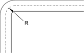
R = 1.5 times the diameter of spiral gaskets. R = 1.5 times the width of the "D" Multi-Seal gasket ("E" dimension).
Dovetailed O-Ring Groove
This groove can either be extruded, or machined using a special dovetail cutter which is available from Spira. When machining this groove, a standard o-ring groove must be machined first. See Dovetail Groove Cutters for more information.
Advantages
- Encourages the shielding performance illustrated in the Shielding Quality data sheets.
- Holds spiral in place.
- Ease of maintenance.
- Facilitates easy field installation.
- Can be incorporated into an extrusion at no extra cost.
Disadvantages
- Approximately 30% higher manufacturing cost than standard o-ring groove.
- Deburring of the top opening on small groove sizes can widen the opening to a point where the spiral may fall out. We recommend that deburring be performed using Scotch Brite or fine sandpaper. DO NOT use a deburring tool.

Uncompressed gasket in dovetailed groove.

Gasket in dovetailed groove compressed by cover.
O-Ring Groove with Adhesive
Use the same groove dimensions as the standard o-ring groove discussed previously. Use very small (1/16”) dots of glue every 3-4” along the groove. Since the glue may degrade the shielding, use as little as possible to hold the gasket in place. You can also minimize shielding degradation by placing the glue dots at fastener locations. We recommend using either super glue, epoxy, or RTV. We do not recommend the use of conductive adhesives since their conductivity tends to degrade over time, thus degrading the shielding and giving you a false indication of the long-term shielding you will achieve. See below for recommended groove dimensions.
Advantages
- Low manufacturing and maintenance costs.
- Holds Spiral in place.
Disadvantages
- Slightly reduced shielding if adhesive is not placed at the fastener location.
- Shielding can be severely reduced if too much adhesive is applied.
- Labor costs to apply adhesive.

Uncompressed gasket in o-ring groove held in place by a dot of adhesive.

Small dots of adhesive every 3-4 inches holds gasket in place.
O-Ring Groove with Pinch Bosses
This is a standard o-ring groove with narrower sections every 2 to 4 inches that “pinch” the spiral in place. Since this groove can be die-cast or molded into an enclosure, it is ideal for use in high-volume cost-sensitive applications.
The figure illustrates suggested dimensions according to the diameter (D) of the gasket. The undercut directly under the pinched area is critical in the design and use of the groove. Contact us for any additional information.
Advantages
- Very cost effective for high volume molded or die cast applications.
- Can effectively be used to eliminate cross- talk on printed circuit boards.
Disadvantages
- Slightly reduced shielding.
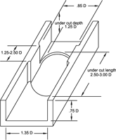
D = Diameter of gasket
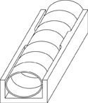
Gasket held in place by pinch boss o-ring groove.
Narrow O-Ring Groove
This groove is only recommended in retrofit situations where the cost or time involved with changing to a more suitable groove is prohibitive. The width of the groove is the same diameter as the gasket. The depth of the groove should be roughly 75% of the diameter of the gasket. The gaskets recommended for the narrow o-ring groove are our “moderate force” gaskets or low force Flexi-Shield.
Advantages
- Good for retrofit situations where a groove already exists.
- Encourages highest shielding attainable for the gasket in use.
- Spiral is not likely to fall out of the groove.
Disadvantages
- Force required to compress gasket is significantly greater. This will increase the number of fasteners required, which in turn increases materials and maintainability costs.
- The force-to-deflection ratio is non-linear, which complicates calculations for fastener placement.
- When the gasket is compressed it will be deformed, so if the gasket is ever removed from the groove it must be replaced.

Uncompressed gasket in o-ring groove of same diameter as gasket.

Gasket compressed in o-ring groove of same diameter as gasket. Note that gasket will be misshapen when removed.
Groove Mounting Other Gaskets
Traditionally, only our spiral type gaskets are recommended for groove mounting. However, almost any type of gasket can be designed into a groove if desired. The important thing to remember is to allow 25% of the diameter of the spiral to protrude above the top of the groove. Also, be sure to choose a groove wide enough to allow the spiral lateral expansion for optimal performance.

Spira-Strip mounted in a groove and held in place by adhesive.

Spira-Strip mounted on groove cut into edge of equipment chassis. A bead of adhesive (on the elastomer only!) holds it in place.
Groove Dimensions
The table below shows the recommended mounting dimensions for commonly used sizes of spiral gaskets. The chart applies to Spira-Shield, Ultra Quick-Shield, Quick-Shield, Flexi-Shield, Endur-o-Shield, and “D” Multi-Seal gaskets. The dash numbers shown can be matched with those in the part number charts of the applicable gasket. We have not included dimensions for the narrow o-ring groove. Generally speaking, a narrow groove is defined as any groove that is narrower than the recommended width of our other o-ring grooves.
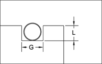 Quick-Shield in an o-ring groove. |
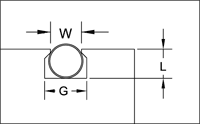 Spira-Shield in a dovetailed o-ring groove. |
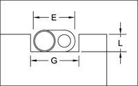 "D" Multi-Seal gaskets in an o-ring groove. |
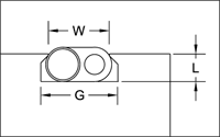 "D" Multi-Seal gasket in a dovetailed o-ring groove. |
The chart applies to the following gaskets:
| Spiral Dash Number | Spiral Diameter "D" | Recommended Mounting Dimensions | ||
| Depth L + .002" -000" (.75D*) | Width G +.007" -.005" (1.35D*) | Width W +000" -.002" |
||
| -02 -03 -04 -.070 -05 -06 -.103 -07 -08 -.139 -09 -11 -12 -16 -20 -24 -32 | .034" .047" .063" .070" .078" .094" .103" .109" .125" .139" .141" .172" .187" .250" .312" .375" .500" | .023" .035" .046" .053" .059" .070" .077" .082" .094" .104" .105" .128" .140" .185" .234" .280" .375" | .046" .063" .094" .094" .109" .125" .141" .156" .171" .187" .187" .234" .250" .343" .422" .500" .667" | .033" .045" .060" .067" .075" .090" .099" .105" .121" .134" .136" .165" .181" .240" .300" .364" .485" |
| "D" Multi-Seal Dash Number | "D" Multi-Seal Width ("E") | Depth L (.75E**) | Width G (1.35E**) | Width W |
| -0421 -0632 -0842 -1263 -1684 | .141" .188" .250" .375" .500" | .046" .070" .094" .140" .185" | .187" .250" .300" .500" .625" | .138" .180" .240" .367" .485" |
* D = Diameter of spiral
** E = Width of "D" Multi-Seal
Surface Preparation
- Minimal surface preparation is required with Spira EMI gaskets. A clean surface will encourage the highest level of shielding attainable.
- For environmental sealing a 32 micron finish is recommended.
Adhesion
- We recommend you do not use conductive sealants with Spira EMI gaskets. Our shielding is achieved through the metal-to-metal contact between the spiral and joint surfaces. Conductive sealants will merely get in the way of this.
- To apply gaskets that do not have adhesive backing, you can use either super glue, epoxy or RTV. Be careful to apply the adhesive only to the rubber portion of the gasket. Do not get glue on the spiral as it will degrade the shielding.
Fastener Placement
Fasteners may be placed on either side of the gasket. Care should be taken to avoid puncturing the spiral. To maintain the integrity of the EMI bond it is important that each fastener is referenced to the chassis by making good metal-to-metal contact. When using the gasket to achieve an environmental seal, care must be taken to ensure that the fastener placement does not compromise this seal.
Excellent Design
Screw makes EMI bond with chassis. Screw going through rubber elastomer maintains the integrity of the environmental seal.

Excellent Design: Gasket held in place with screw and nutplate.
Good Design
The risk of moisture leak is minimized by the use of a rubber washer. The metal nutplate ensures that the screw will be referenced to the chassis to maintain the integrity of the EMI seal.

Good Design: Gasket held in place with screw, nutplate and one rubber washer.
Poor Design
The use of two rubber washers insulates against environmental leakage, but also prevents the screw from being referenced to the chassis. This creates an EMI "hole" and can significantly degrade the shielding quality of the joint.

Poor Design: Gasket held in place with screw, nutplate and two rubber washers.
Poor Design
Moisture can leak through the screw hole, compromising the environmental seal.

Poor Design: Gasket held in place with screw and nutplate.
The following gaskets can be surface mounted:
Information for other gaskets is available in Groove Mounting Techniques.
