Shielding Theory & Data
EMI Shielding Quality Data
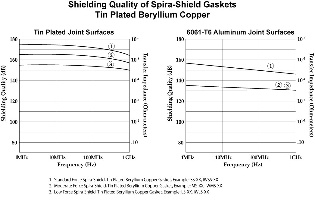
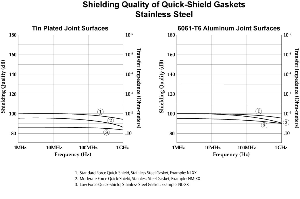
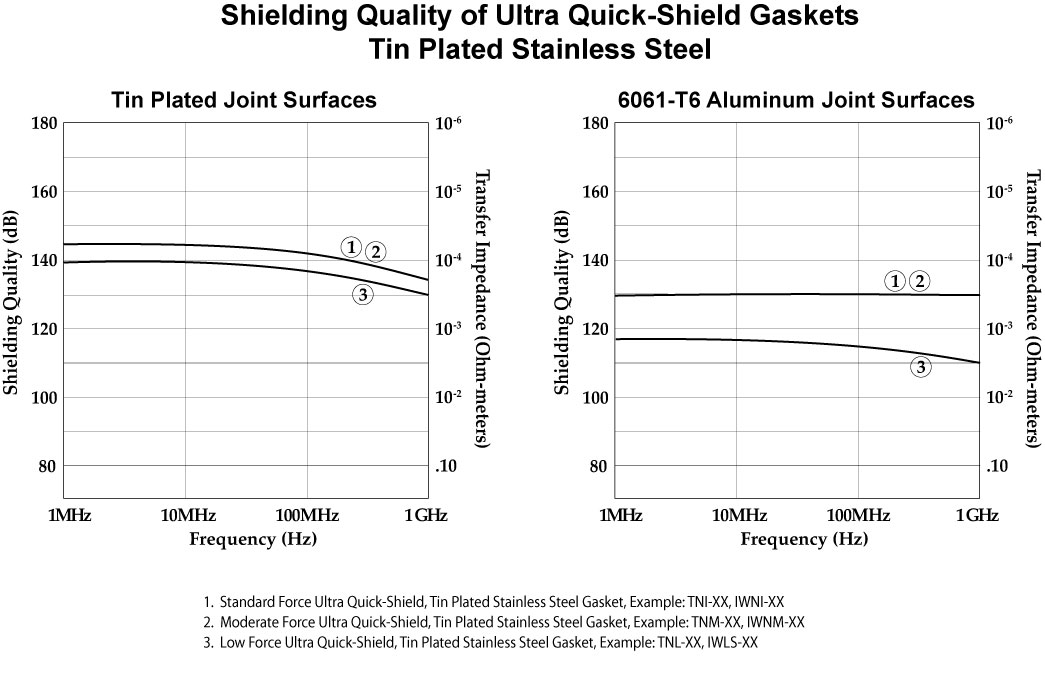
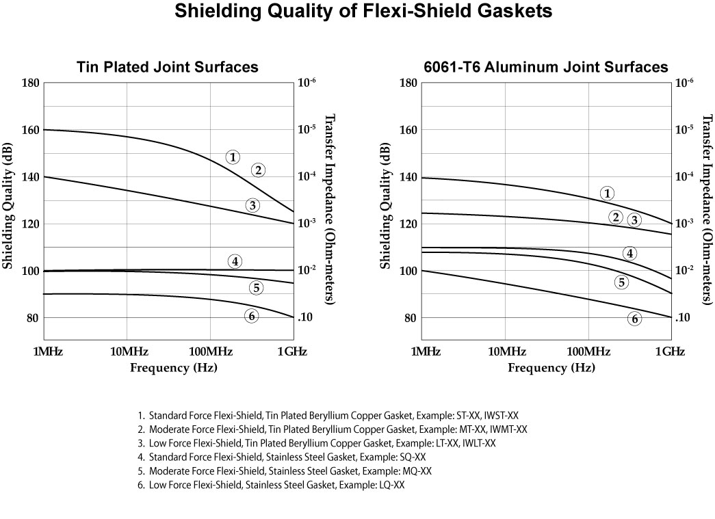
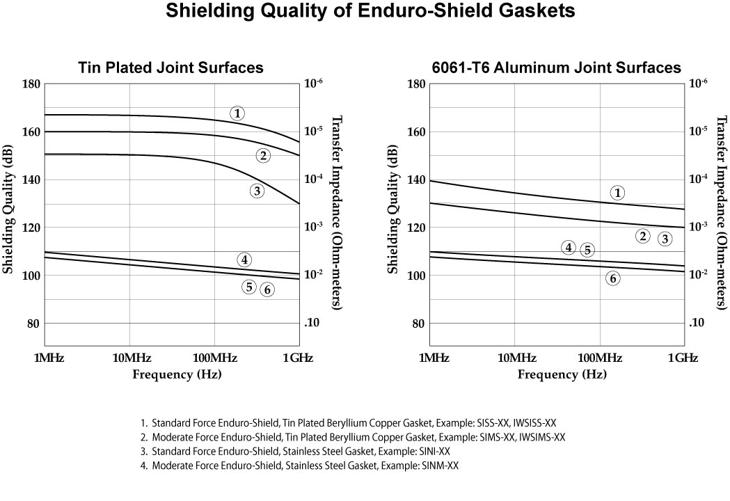
Shielding quality data is shown for each of the different types of spiral gaskets that are available either as standalone products, or attached to substrates.
Spira-Shield Gaskets
Quick-Shield Gaskets
Ultra Quick-Shield Gaskets
Flexi-Shield Gaskets
Enduro-Shield Gaskets
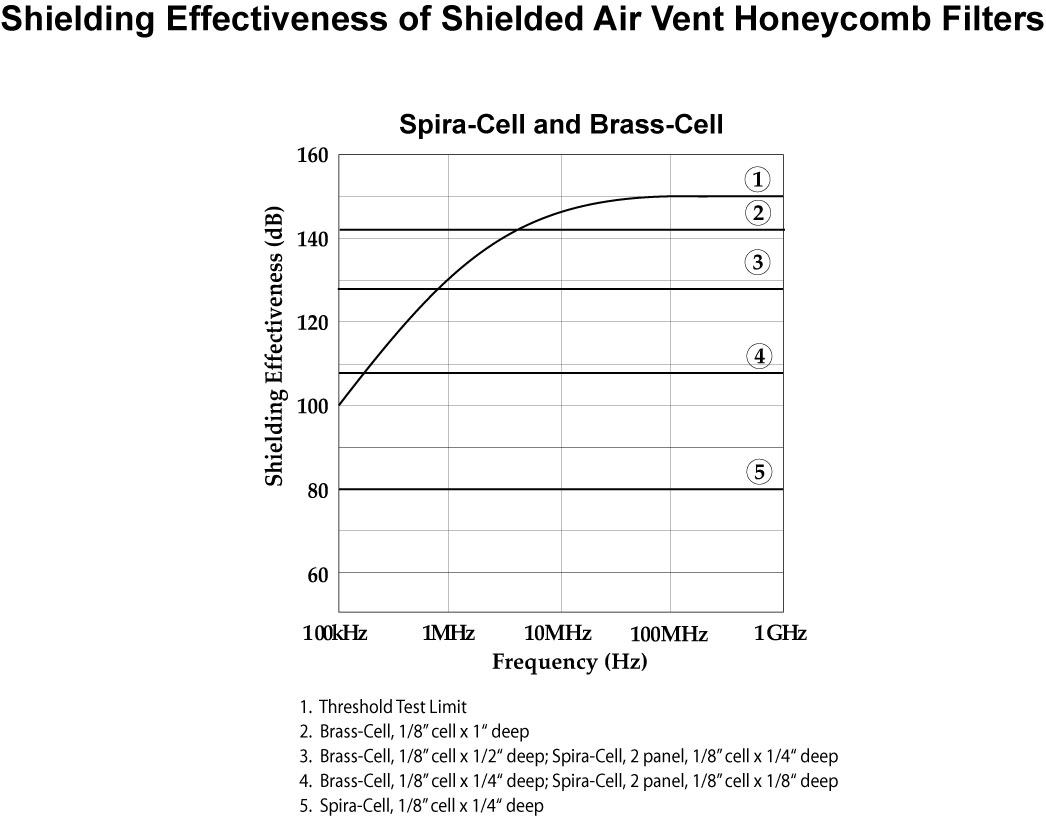
Shielded Honeycomb Air Vent Filters
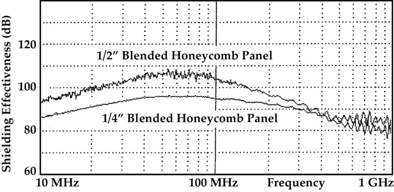
Shielded Honeycomb Fan Filters
Why We Use Transfer Impedance Testing
There are two industry-accepted methods for testing the shielding capability of EMI gaskets. These are: (1) Shielding Effectiveness (as defined in MIL-G-83528), and (2) Transfer Impedance as defined in SAE ARP-1705 Rev A.
The Shielding Effectiveness test was designed by one of the EMI gasket manufacturers and it has inherent test anomalies, which erroneous report extremely high levels of shielding for the products under test. As an example, tests performed at 2 GHz illustrated “Shielding Effectiveness” test results in excess of 120 dB using no gasket between the enclosure and cover specified in the test procedure. Placing a sheet of non-conductive newspaper as a “gasket”between the cover and shielded enclosure provided 93 dB of shielding. Transfer Impedance as a method of testing EMI gasket was derived from the academic community.
Transfer Impedance measures the impedance of a gasket and gasketed joint. The procedure for measuring transfer impedance of gaskets (or gasketed joints) is detailed in SAE, ARP-1705 Rev A dated January 1, 2006.
The test data that follows has been done using Spira’s ZT-1000 Transfer Impedance Test Fixture[link to product page –or show related products below?], a spectrum analyzer, and a printer.
Joint Surfaces Are Important
In the data shown on the following pages we have illustrated the transfer impedance (and subsequent Shielding Quality) of the gaskets against two surfaces: tin plated aluminum and 6061-T6 aluminum. This is presented to illustrate the importance of selecting a gasket that will provide the required shielding using the specific joint surfaces of concern.
Test Conditions
All test data consists of new gaskets and freshly cleaned joint surfaces in a controlled temperature, low humidity office environment. Aging and/or environmental conditions may deteriorate the level of shielding provided by a gasket in conjunction with specific joint surfaces.
Note: This data is representative of the test data we have obtained. Your results will vary depending on the applicable variables.
Shielding Quality
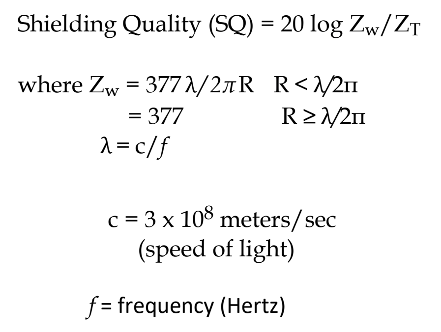
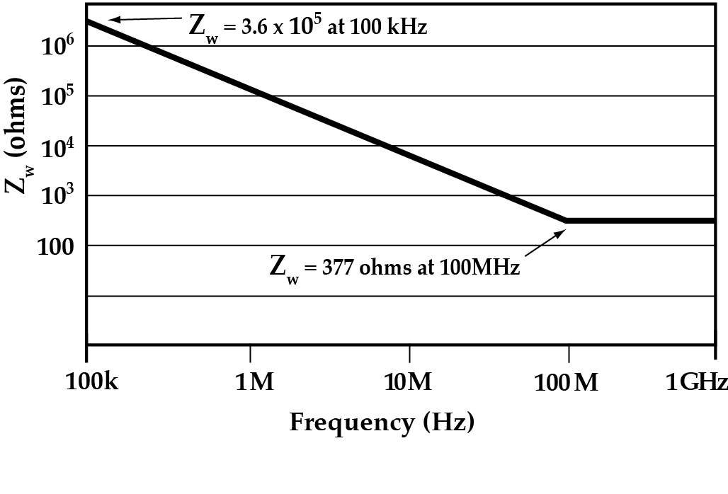
Shielding quality as defined in SAE, ARP-1705 Rev A is the theoretical “Shielding Effectiveness” of the gasket and gasketed joint using the conditions and constraints of shielding theory and MIL-STD-285. The definition as listed in ARP-1705 Rev A is illustrated below. The shielding quality data illustrated in the pages that follow assume that the incident wave is a plane wave having an impedance of 377 ohms.
 |
 Zw using constraints consistent with MIL-STD-285 Zw using constraints consistent with MIL-STD-285 |
* We use 377 as the wave impedance for all calculations to simplify computation.
Shielding Effectiveness of Shielded Honeycomb Filters
The shielding effectiveness testing of Spira’s honeycomb filters is performed by generating an electromagnetic field through a hole in an enclosure and recording the field strength. The honeycomb filter under test is then attached to the enclosure and a second field strength measurement is recorded. The shielding effectiveness is the difference in the recorded field strength readings in dB.Shielding Effectiveness of Shielded Air Vent Honeycomb Filters
EMI Shielding Theory
There are two ways of approaching the theory of shielding: the use of circuit theory, or the use of wave theory. The EMC industry uses a wave theory approach to shielding theory using abstract mathematical modeling techniques to yield a value of merit classified as “shielding effectiveness”. Shielding effectiveness is then used as a measurement to gauge the attenuation of the Electromagnetic (EM) fields through shielding barrier material.
The problem with the use of shielding effectiveness is that there can be a significant differential between the attenuation of the electric E fields, magnetic H fields, and power, where the difference can exceed 100 dB. The actual difference will vary as a function of variables associated with specific applications where the literature on the shielding of radiated EM fields does not address these conditions. The result is a significant confusion factor in the selection of shielding barrier material, facing design engineers who are required to meet EMC radiated emission and susceptibility requirements.
The circuit theory approach (included herein) employs mathematical modeling techniques consistent with college course work and yields a predicted field strength at any given distance from the shielding barrier material. The results can also be used to predict the shielding of a seam or gasketed joint in the barrier material (or enclosure). The circuit theory approach given below examines the wave as it penetrates a barrier and yields a value of the E and H fields as the wave exits the barrier.
Introduction

Figure 1
A radiated electromagnetic (EM) wave is generated by the action of driving a current through a wire. An example is that of Figure 1 which represents a sending/receiver circuit on a PC card.
The wire (or PC card trace) acts as a transmitting antenna, as an emitter of EM interference and as a receptor with regard to EM susceptibility. A common method of reducing (or eliminating) the possibility of the PC trace being an emitter or receptor is by the use of a shielding barrier.
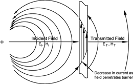
Figure 2
When an EM wave is impinged on a metallic (conductive) shielding barrier, currents are caused to flow in the barrier. As the wave penetrates the barrier, the current is attenuated (i.e., reduced in amplitude as illustrated in Figure 2) by a force called skin effect.
The power of the wave as it leaves the barrier is approximately equal to the current squared times the impedance of the barrier, and is in watts per meter squared.
As we learned above, currents flow in the shielding barrier as a function of the radiated wave being impinged on the barrier. When the current crosses a seam in the barrier (created by maintenance covers, etc.), a voltage is created across the seam, where the value of the voltage is equal to the current times the impedance of the seam. The seam then becomes a radiating antenna where the impedance and pattern is similar to that of a slot antenna. EMI gaskets are used to reduce the impedance of the seam and subsequent power radiating from the seam.
Generation and Propagation of EM Fields
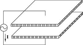
Figure 3
The undergraduate courses on EM theory introduce the concept of an EM wave by driving a pair of parallel plates with an AC voltage source as illustrated in Figure 3. The current that flows through the wire comes from the top plate and is stored in the bottom plate. The over-presence of the electrons on the bottom plate is illustrated by ![]() and the absence of electrons on the top plate and is illustrated by
and the absence of electrons on the top plate and is illustrated by ![]() . This creates an EM wave which is illustrated in Figure 4. The EM wave consisting of the straight lines is classified as a displacement field and is in Amperes per meter squared. The magnitude of the E field is equal to the voltage differential between the plates divided by the distance between the plates in meters. The resultant E field is in Volts per meter (e.g., a set of parallel plates is used for performing E field susceptibility testing to MIL-STD-461/462).
. This creates an EM wave which is illustrated in Figure 4. The EM wave consisting of the straight lines is classified as a displacement field and is in Amperes per meter squared. The magnitude of the E field is equal to the voltage differential between the plates divided by the distance between the plates in meters. The resultant E field is in Volts per meter (e.g., a set of parallel plates is used for performing E field susceptibility testing to MIL-STD-461/462).
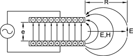
Figure 4
As is illustrated in Figure 4, the lines of flux in the center of the plates are straight and flow from the bottom to the top plate. At the edges they bow out, where the fields or lines of flux repel each other, forcing the bowing. The field that bows out represents a radiated EM wave. The radiated EM wave emanating from the trace of Figure 1 is similar to the radiated EM wave illustrated in Figure 4. The electric “E” field is tangent to the lines of flux (displacement current) as illustrated in Figure 4. The magnetic “H” field is a field perpendicular to the displacement current and points out of the paper (right hand rule).
The set of plates as illustrated in Figure 4 produce a field similar to that of the PC card trace of Figure 1 (and of an electric dipole antenna). If the transmitted power is known, the field strength can be calculated using the dipole antenna equation, i.e.,

And power equation (poynting vector):

If the power is not known, the value of the electric field can be approximated using the following equation:

Suppression (Shielding) of EM Fields
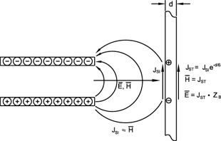
Figure 5
When we place a shielding barrier in the path of the EM wave, the force of the wave causes current to flow in the barrier. As is illustrated in Figure 5, the excess electrons in the bottom plate create a force on the electrons in the barrier. This force causes the electrons to flow away from the point of contact. In a similar manner, the lack of electrons on the upper plate will create an excess of electrons on the barrier at the upper point of contact. This current flow in the barrier is called the "surface current density" ![]() in amperes/meter, and is approximately equal to the H field incident on the barrier when the direction of the wave is perpendicular to the barrier. The current flowing in the barrier is attenuated by skin effect.
in amperes/meter, and is approximately equal to the H field incident on the barrier when the direction of the wave is perpendicular to the barrier. The current flowing in the barrier is attenuated by skin effect.
The current on the transmitted side is equal to ![]() (i.e., the current on the incident side attenuated by skin effect). The impedance of the field emanating from the barrier is equal to the impedance of the barrier. The values of
(i.e., the current on the incident side attenuated by skin effect). The impedance of the field emanating from the barrier is equal to the impedance of the barrier. The values of ![]() and
and ![]() are as illustrated in Figure 5 and are as follows.
are as illustrated in Figure 5 and are as follows.
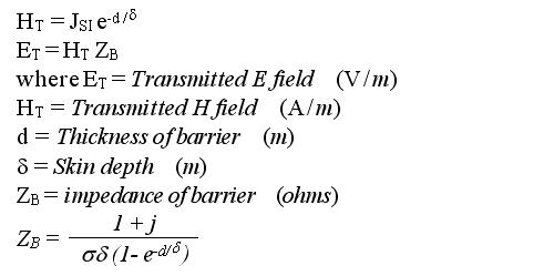
Field Strength Through Shield
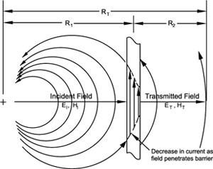
Figure 6
From antenna theory we know that the power from an antenna is reduced as the square of the distance from its source. Shielding theory proposes that the wave as it passes through a barrier is attenuated but not changed with regard to direction. As such, the loss of power is a function of the distance from the original source of the wave as illustrated in Figure 6.
The power at a distance ![]() from the barrier is equal to the following:
from the barrier is equal to the following:

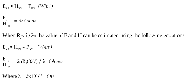
The impedance of the field will vary from a low impedance (impedance of the barrier) to 377 ohms when the distance ![]() . The value of E and H can be closely approximated at a distance
. The value of E and H can be closely approximated at a distance ![]() using the following equalities:
using the following equalities:
Gasketed Joint Shielding
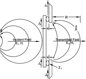
Figure 7
When a radiated EM wave is impinged on a metallic shielding barrier, a current (surface current density in amps/meter) is generated in the material. When the current flows across a gasketed maintenance cover as illustrated in Figure 7, a voltage e is generated across the gasket. The value of e is equal to the current in amps/meter times the impedance of the joint (transfer impedance in ohm-meters).
The EM force field illustrated in Figure 7 is generated by the voltage across the gap and has the characteristics of a low impedance slot antenna.
The value of the radiated EM fields can be estimated from the example of Figure 7 as follows:


